 (equation 1)
Free Space Propagation and the Two Ray Model
In the absence of any reflections or multipath, radio wave propagation can be modeled using the free space propagation model which says:
(equation 1)
where:
Alternatively we can express equation 1 in dB units by taking 10 log 10 of both sides to obtain:
 (equation 2)
The last two terms of equation 2 combined are called Path Loss (PL) for free space propagation. This is the channel's loss in going from the transmitter to the receiver expressed in dB. The first two right hand terms combined is called Effective Isotropic Radiated Power or EIRP. EIRP is the equivalent transmitter power required if an isotropic (0 dBi) antenna were used. Using these definitions, we obtain equation 3 where for free space propagation; PL (dB) = -20 log10 ( l / 4pd)
![]() (equation 3)
(equation 3)
For non free space propagation conditions, PL might be described by PL=A+B log 10 (R) as discussed in Statistical Propagation Modeling for Cellular Systems. To understand why free space propagation usually doesn't apply at extended ranges in the ground mobile environment, let's consider the two ray propagation model.
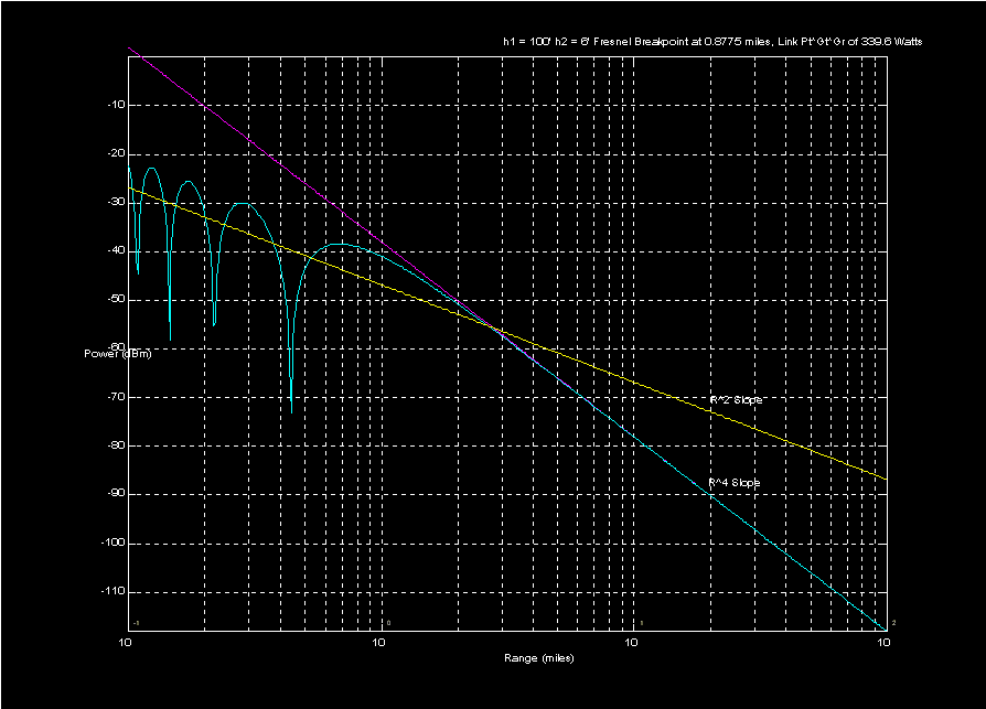
The two-ray model of propagation is discussed in Lee (ISBN 0-07-037039) in section 3. In particular, he considers a model where the receiving antenna sees a direct path signal as well as a signal reflected off the ground. Specular reflection much like light off of a mirror is assumed and to a very close approximation, the specular reflection arrives with strength equal to that of the direct path signal. The reflected signal shows up with a delay relative to the direct path signal and as a consequence, may add constructively (in phase) or destructively (out of phase). In his equation 3-34 (page 101), Lee predicts received power as a function of range. Figure 1 below plots his equation (cyan line) for specific transmit and receive antenna heights at a 1900 MHz center frequency. Note how propagation starts out with an R2 falloff rate and then transitions to a R4 falloff rate at greater ranges. The "point" where this transition occurs is often called the Fresnel breakpoint. The nulls are representative of points where direct and reflected signals cancel while the humps show points where signals add. In practice, ground reflections are usually somewhat diffuse (rough mirror instead of polished) and so the sharp nulls get filled in. In macrocellular communications systems, operating distances are usually large enough so that signal strength can be thought of as falling off at an R4 rate.
Figure 1: Two ray propagation where transmit antenna is at 100' and receive antenna is at 6'
This page created 5 October 1997, all rights reserved to Logan Scott, copyright 1997