
Repeater Gain and Power Requirements for Radar Jamming
Repeater Jamming (RJ) is useful in obscuring real targets by creating multiple false targets in victim radar systems. The basic idea is to receive signals from the victim radar and transmit them back at higher powers to create false target readings. Repeater jamming is most effective when the repeater can hear victim sidelobe transmissions and send them back with sufficient power so that the repeater's transmissions enter the victim radar through its receive pattern sidelobes. Done properly, the victim radar will indicate false targets at angles other than the true angle to the RJ.
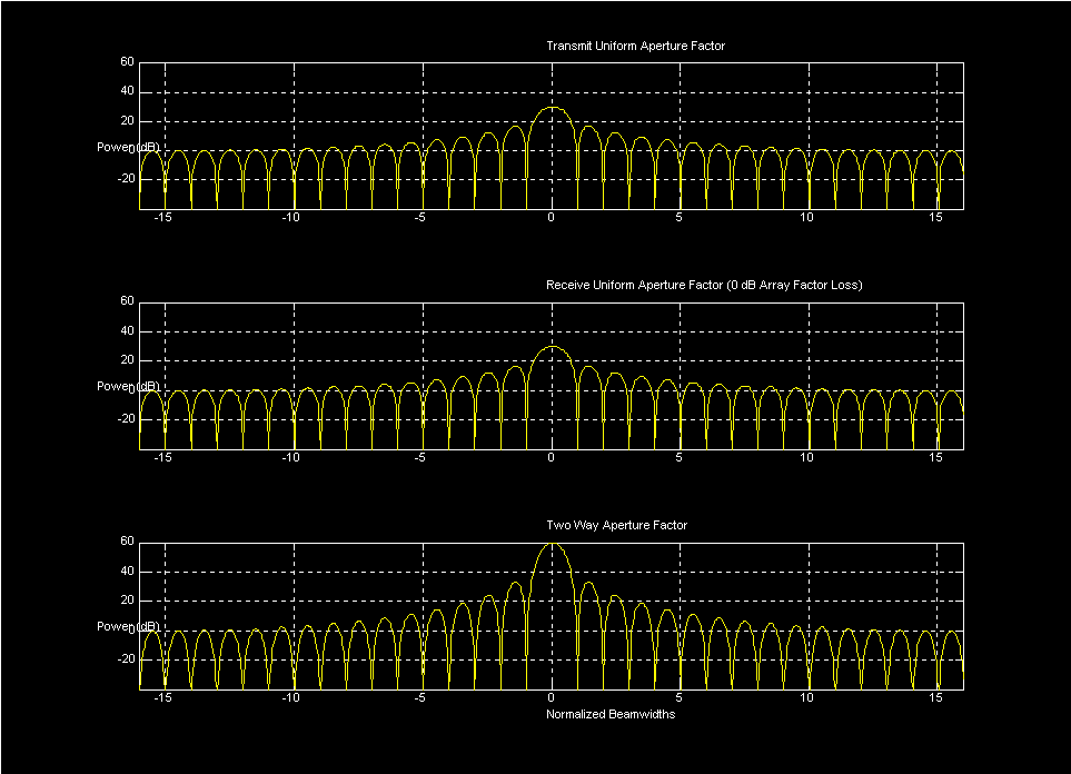
By their very nature, sidelobe transmissions are much weaker than mainbeam transmissions and so more repeater gain is required. This is especially true if low sidelobe tapers are used. Figure 1 shows victim radar transmit and receive antenna patterns assuming a uniform illumination function for the antenna and a 30 dBi nominal gain. The two way pattern is also shown.
Figure 1: Aperture Patterns for Uniform Illumination Tx/Rx Radar
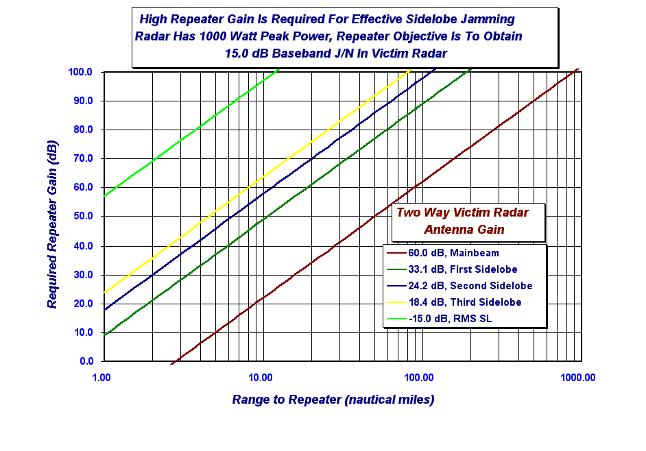
Under these assumptions, Figure 2 shows required repeater gain needed to generate false targets with an apparent SNR of 15 dB as a function of range. The victim radar operates at 10.2 GHz (X-band) and has 8 dB of miscellaneous SNR losses before detection. Free space propagation is assumed. Clutter effects are not considered; the false targets are assumed to be in clutter free regions of the range/doppler map. Considering the Mainbeam case for the moment, if the victim radar has a 30 dBi transmit antenna gain and uses the same pattern on receive, the two way Mainbeam antenna gain is 30dB + 30dB = 60dB. In this case the RJ would need 62 dB of gain to create a false target of 15 dB J/N at a range of 100 nautical miles. While this may not sound like much gain, keep in mind that a simple "bent pipe" repeater would need to receive the signal and then retransmit it (presumably using another antenna) while maintaining >62 dB of isolation between the receive and transmit antennas. Otherwise the repeater will experience positive feedback and oscillate. In sidelobe regions, even higher repeater gains are needed to be effective.
Figure 2: Required Repeater Gain As a Function of Distance for Uniform Illumination Tx/Rx Radar
To mitigate isolation requirements, lookthrough configurations are often used where the RJ takes advantage of the fact that most radar types do not transmit continuously. Here, the RJ listens to the victim radar's transmission and tries to capture a copy of the victim's waveform; usually using a high resolution A/D converter. The sampled waveform is then used to generate false target waveforms for transmission back to the victim radar. By using a sampled version of the waveform, we avoid the need for simultaneous reception and transmission at the same frequency. Lock on time is a key driver for lookthrough repeater jammers. This is especially true when operating against frequency hopping radars. There may be limited analysis time since signals sent back too late may not be received by the victim radar; the victim radar may have already shifted to another frequency.
Figure 3 shows required RJ Effective Isotropic Radiated Power (EIRP) needed to obtain a 15 dB baseband J/N in the victim radar as a function of range. Clearly, the lookthrough RJ will not need to generate a lot of power in order to jam the victim radar when operating in the close in sidelobe region. To counter this, most modern radars use low sidelobe tapers; particularly on receive.
Figure 3: Required Repeater EIRP As a Function of Distance for Uniform Illumination Tx/Rx Radar
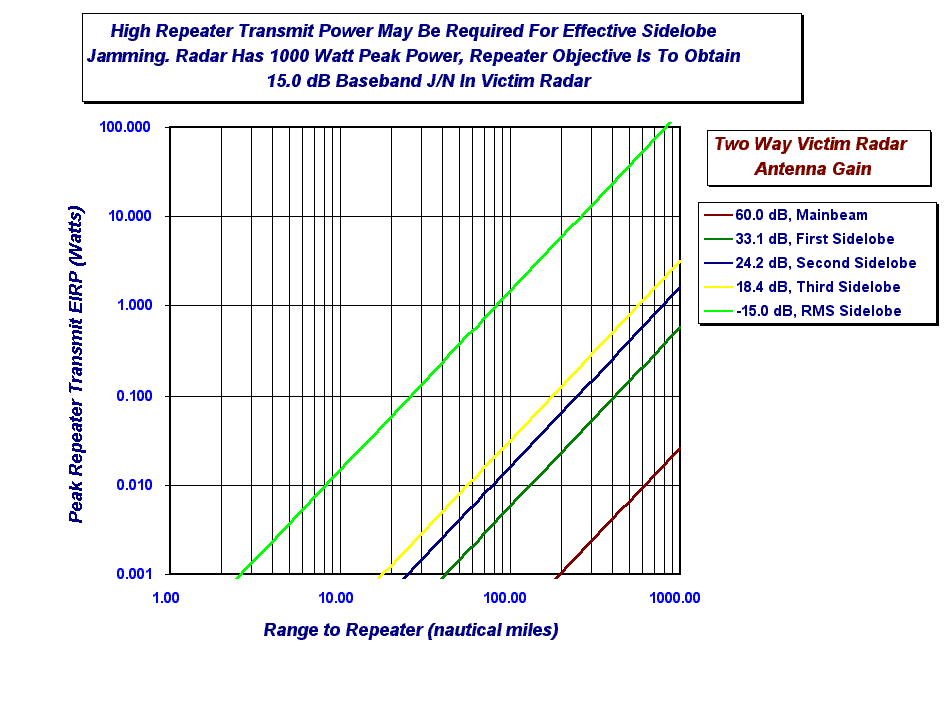
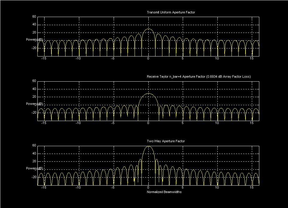
Figure 4 shows transmit and receive antenna patterns typical of a modern active phased array radar. The transmit pattern continues with a uniform illumination function mainly because there is a double penalty in trying to use low sidelobe tapers on transmit. Not only do you loose directive gain due to the illumination taper but you also loose transmit power because elements located out towards the edge don't transmit at full power. On receive, a Taylor n_bar = 4, 30 dB sidelobe taper is used. There is a 0.7 dB antenna gain penalty associated with this taper but close in sidelobe are much lower. Looking at the two way pattern; the first sidelobe is at 26 dBi, the second is at 13 dBi, and the third is at 7 dBi. Monopulse radars might use a Bayliss taper for the difference pattern to obtain low off-boresight sidelobe levels.
Figure 4: Aperture Patterns for Uniform Illumination Tx/ Taylor n_bar=4 Illumination Rx Radar
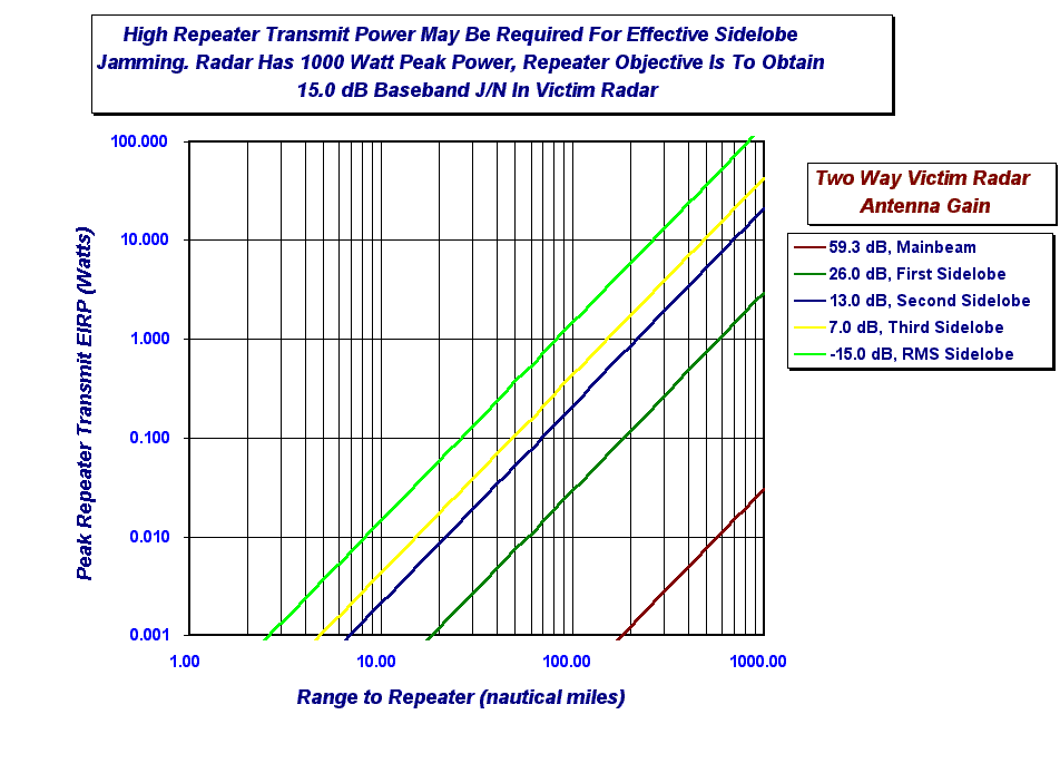
Refering to Figure 5, we now see considerably higher repeater gains are needed to be effective once we get out past the first sidelobe. Corresponding peak EIRP values are shown in Figure 6.
Figure 5: Required Repeater Gain As a Function of Distance for Uniform Illumination Tx/Taylor n_bar=4 Rx Radar

Figure 6: Required Repeater EIRP As a Function of Distance for Uniform Illumination Tx/Taylor n_bar=4 Rx Radar
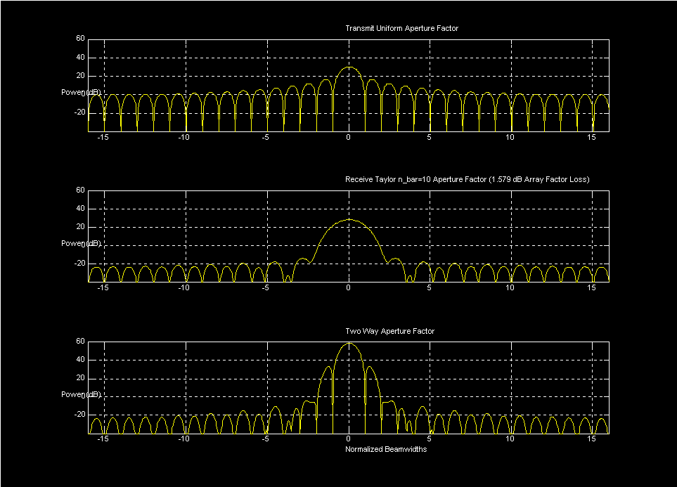
In the event that very low receive sidelobes are desired, we might consider the lower sidelobe receive patterns of Figure 7. Here, a Taylor n_bar=10, 50 dB sidelobe taper is used but with an additional 0.9 dB loss in antenna gain. In situations where sidelobe jamming is a problem, it may be worthwhile for the radar to switch in a low sidelobe taper and accept the lowered sensitivity.
Figure 7: Aperture Patterns for Uniform Illumination Tx/ Taylor n_bar=10 Illumination Rx Radar
Of course, as Figure 8 shows, maintaining very low sidelobe levels will require very accurate module calibration and low failure rates.
Figure 7: Aperture Patterns for Uniform Illumination Tx/ Taylor n_bar=10 Illumination Rx Radar
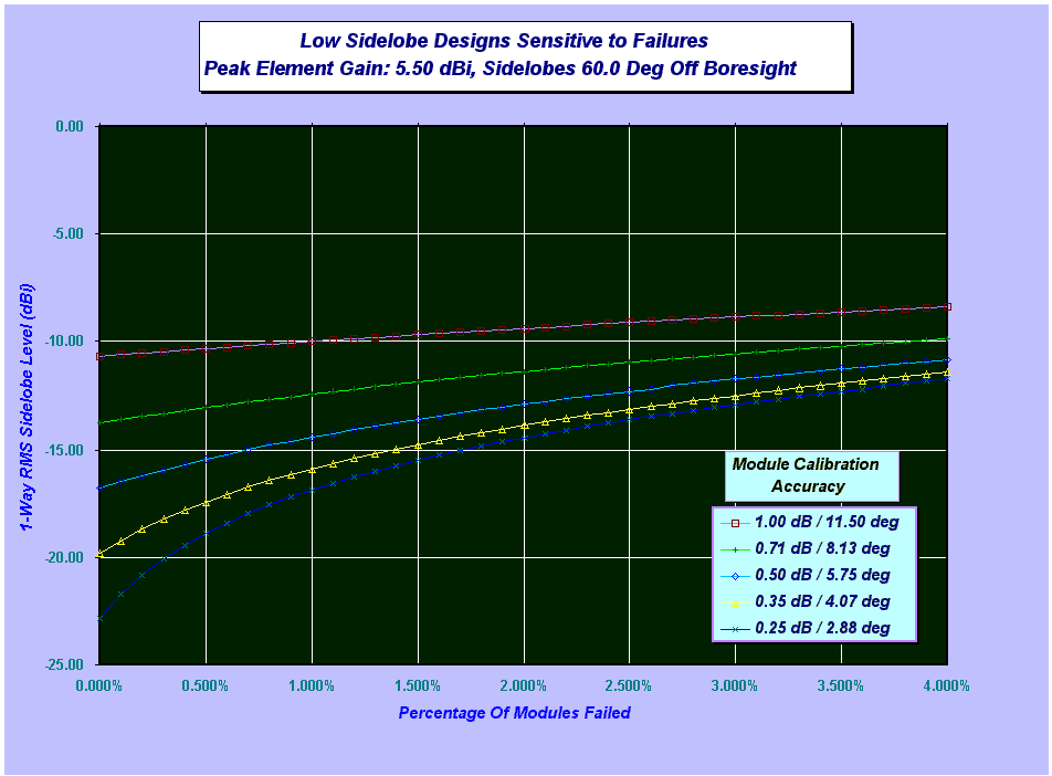
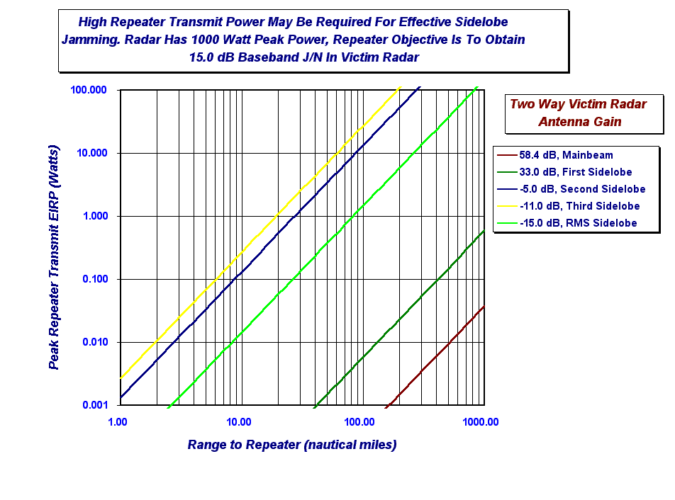
Figure 9 shows that with very low sidelobe receive patterns, RJ EIRP values are still very doable with lookthrough jamming approaches. It should also be noted that sidelobe blanking techniques may be used by the victim radar to mitigate RJ false targets.
Figure 9: Required Repeater EIRP As a Function of Distance for Uniform Illumination Tx/Taylor n_bar=10 Rx Radar
This page created 24 October 1997, all rights reserved to Logan Scott, copyright 1997
For more information on how
I can help you with your specific system, contact me via my homepage or via e-mail at:
![]()